Time to put the group together!
Last time I installed piston rings it took me a couple of hours and there were chopsticks, screwdrivers and swearing involved. With that experience in mind I came up with this little device to take the hassle out of the task. The thin lip at the bottom that fits over the outer diameter of the group is very fragile and will eventually have to be replaced with some metal but now I can put on a set of seals with my bare hands in 30 seconds!
Now it is really time to put the group together.
Having spending hours faffing around with threaded rods and myriad nuts and washers the last few times around, this time I decided use the milling machine vise to compress the spring.
Spring compressed and pin in place.
First completed assembly from new parts!
Everything works as it should, but I don't have any more pictures, for reasons that will become clear below.
Compressing the spring with the milling vise worked but it was only marginally faster than the threaded rod method and, more importantly, it means that all work has to be done with the assembly in the vise. Furthermore, the pin had to be driven into place with no support behind the cam - a very, very bad idea as I found out when I broke the fork while I was disassembling it.
So what did we learn? One, that it isn't a good idea to do anything on Fridays at 5. Two, don't use the milling vise to compress the spring. Three, that the 8mm off-the-shelf knurled pin that I found just doesn't cut it. First, I could only find 8x30 and the missing 2mm that aren't holding the spring makes me nervous and second, the extra millimeter in diameter makes the difference between the pin clearing the top of the bearing plate posts or not - making installation harder. This is a pain as the 7x32 pin that Brugnetti used is emphatically non-standard. They had some factory make 10,000 of them and forgot about the problem - which I guess is what I will do too :).
Today's post on the lever cam is, I think, a fairly significant milestone on the build: the very last pre-production prototype.
That means that I have now made at least one of every single part of the machine!
Although, like the brew reservoir, the production version will be cast in bronze, I wanted a dimensional prototype to make sure everything fits together. The idea here is to make a functional part that will be used to test the production techniques, tolerances, fit of the part in the piston assembly and the assembly method itself. Though it has to work at least briefly to test the assembly, certain "best practices" can be ignored. In other words: any goes ;)
I start with a scrap of mic6 tooling plate that was leftover from another project. The bottom few millimeters of the block are clamped in the vise and, using a roughing endmill, I cut the basic profile of the clevis or fork.
Then I move to a finishing endmill for the last pass.
Two starting pilot holes for the bearing shafts and the pin.
and, after changing setup of the support blocks underneath, the two holes are first drilled close to the final diameter and then reamed to get a good tolerance.
Then it is time to flip the part over and remove the sacrificial base that was in the vise.
Then the block is rotated in the vise again to cut the space between the forks.
Fork!
Next up, the bearing shafts. These are turned from my new friend: 7075 aluminum. Faster than a speeding bullet. Able to bend steel with its bare hands... etc. I ground down a cut-off blade to make the very narrow groove for the retaining ring.
The design guides for bearings call for a fairly tight tolerance on the shaft (I wont go into a rant here on the Byzantine naming conventions for fits). Suffice it to say that Brugnetti (or at least the guy on the shop floor that day) ignored the design guides and I did not.
The shafts are then finished with a slightly over-sized hub to provide an interference fit with the holes in the clevis. Then they are driven into the fork with a soft hammer.
Shafts in place. (I goofed on the length of the first hub, which was supposed to be flush with the inside of the fork wall).
The last piece of the weldment is the receiver for the lever shaft. Again in 7075.
I cut the negative of the top of the fork block in the end of the tube to make a decent fit prior to welding and then the part goes back to the lathe for the internal threading.
So, the metallurgically (that's not a word but never mind) inclined who have been following thus far are saying: "haha - he doesn't know that you can't weld 7075 aluminum!" Well, I say to them: "Yes you can. It is just not a very good idea." ;).
Here is a test weld using 5xxx alloy filler material to join some 7075 rod to a 6061 plate.
And to show that "micro-cracking" is actually "micro-cracking my ^@&^%":
In all seriousness however, this is not how this should be done.
But this is just a test... so I'm just gonna weld this mess together:
Mediocre welding technique aside (anyone looked closely at a Cannondale bike frame?), what was many is now one.
And polishing makes it look, if not perfect, then just a wee bit better.
One test cam? Check!
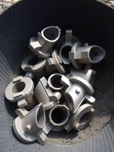
Today's installment is the first foundry production part: the brew reservoir. I made the prototype entirely from discrete stainless parts, but the complex form means that it is much more efficient to make a casting.
The prototype reservoir from 2016.
After a lengthy exchange with the foundry: one bucket-o-castings! Slightly more costly than KFC.
The rectangular blocks on the face of the flange are casting "risers" that provide a reservoir of liquid metal that is drawn into the casting as it solidifies to prevent internal voids from forming.
The large void in the surface means that this one is likely a reject and will go back into the melting pot.
A few days later and the parts arrived at my shop. So easy!
As the foundry molds have to be made anyway, I thought I may as well add the detail of the threaded nub on the side of the reservoir. This is an easy place to unobtrusively attach a thermocouple - the data from which may or may not be useful. Time will tell.
Happy New Year!
Tons of progress over the last few weeks. I have lots to report, but the first post of 2018 is the last part of the piston build which I started before the holiday.
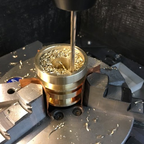
Unlike the other parts of the piston assembly, the head is a wetted surface and consequently needs to be made from a lead-free material. I bought some 2" diameter C69000 quite a long time ago for this purpose, but it has taken a while to get to it. Partly, this is because this stuff is expensive (even for brass). I also have to get it from the states, which is a huge added expense and hassle. SO: no mistakes!
The rough diameter is pretty close to the diameter of the piston so I have to chuck the stock carefully to avoid excessive run-out. Unfortunately, it is too large for the internal bore of my trusty 6-jaw so I have to use the 4-jaw annoyance.
Remove a little material to get close to the desired piston diameter (close in this case is within 0.001"). Then the last thousandth is removed with a sanding block and a succession of grits (from 400 all the way to 2000). This puts the P in precision as far as my shop is concerned.
Then we add the seal and relief grooves.
Once the grooves are finished, the internal bores at the top end are added.
And, after chamfering all the sharp edges, the piston head can be cut off from the stock.
The lathe work done, the part is put on the mill to drill the mounting holes on the top side. The copper foil is to prevent the steel chuck jaws from marring the hard-won surface finish of the flanges.
... and the pressure vents on the bottom. Having said NO mistakes, I then made one here. If you look carefully, you can see a seventh centre-drill mark where I drew an extra point for construction in the CAM file and forgot to erase it. Fortunately, this is just cosmetic as it doesn't pass through the flange.
A better shot of the vents.
Here is the collection of the parts for the assembly: the piston rod plus floating head, the piston head, three stainless machine screws and washers and an 8mm dowel pin (more on this last part another day). The little red arrow shows the relief groove that the washers will fit into to keep the head in place.
A close up of the connection detail with the washer in place.
And, the free-to-wiggle result!