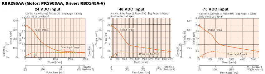
The original motors for the mill are from another project. They are at the very limit of usability in terms of the maximum torque they deliver at low rpm. With the current 24v power supply, the torque drops off very quickly. Time to upgrade!
Current motors: Vexta PK296DAA

Inductance : 1.5 (bipolar) mH per phase
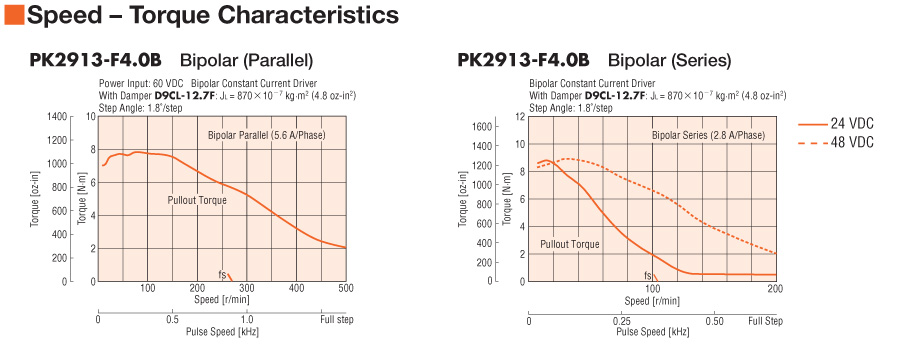
New motors: Vexta PK2913 E4.0A

Inductance: 4.2 [Bipolar (Parallel)] 16.8 [Bipolar (Series)] 4.2 [Unipolar] mH per phase
_________________
Excellent article about power supplies:
http://www.geckodrive.com/support/step-motor-basics/power-supply-basics.html
Calculating the maximum voltage for a stepper from its inductance:
Vmax = 32*√L where L is the motor inductance in milliHenries
So the maximum voltage for the original 296DAA steppers is 32*√1.5 = 39v
If the new 2913E4 motors are wired in parallel, the maximum voltage for the is:
32*√4.2 = 65.6v
The nearest standard output voltage from Antek is 63 volts.
A motor control will always draw less than 2/3 of the motor’s rated current when it is parallel (or half-winding) connected and 1/3 of the motor’s rated current when it is series (or full-winding) connected. That is to say, a 6 amp per phase motor will require a 4 amp power supply when wired in parallel and a 2 amp power supply when wired in series.
Wired in bipolar parallel, the motor is rated at 5.6 amps per phase. So the amperage required per motor is 2/3 x 5.6 = 3.73 amps
Total amperage required for three motors is 11.2 amps, four would be ~15 amps.
The closest 15 amp Antek model is this one:
PS-10N63 - 1000W 63V POWER SUPPLY $162.00
_______________________

Connector seen from front
O
Blk o o Grn
Wht o o Red
Blk -> Blu Wht Grn -> Grn Yel
Wht -> Ren Tan Ren -> Blk Pink
NB - the connectors used are not wired consistently because of mistakes in the control panel cables. Coil A are pins 1&3 on the motor connector and Coil B 2&4. Check the continuity from the output of the gecko drive to the connector pins.
Current motors: Vexta PK296DAA
Inductance : 1.5 (bipolar) mH per phase
New motors: Vexta PK2913 E4.0A
Inductance: 4.2 [Bipolar (Parallel)] 16.8 [Bipolar (Series)] 4.2 [Unipolar] mH per phase
_________________
Excellent article about power supplies:
http://www.geckodrive.com/support/step-motor-basics/power-supply-basics.html
Vmax = 32*√L where L is the motor inductance in milliHenries
So the maximum voltage for the original 296DAA steppers is 32*√1.5 = 39v
If the new 2913E4 motors are wired in parallel, the maximum voltage for the is:
32*√4.2 = 65.6v
The nearest standard output voltage from Antek is 63 volts.
A motor control will always draw less than 2/3 of the motor’s rated current when it is parallel (or half-winding) connected and 1/3 of the motor’s rated current when it is series (or full-winding) connected. That is to say, a 6 amp per phase motor will require a 4 amp power supply when wired in parallel and a 2 amp power supply when wired in series.
Wired in bipolar parallel, the motor is rated at 5.6 amps per phase. So the amperage required per motor is 2/3 x 5.6 = 3.73 amps
Total amperage required for three motors is 11.2 amps, four would be ~15 amps.
The closest 15 amp Antek model is this one:
PS-10N63 - 1000W 63V POWER SUPPLY $162.00
_______________________
2913E motor wiring
Connector seen from front
O
Blk o o Grn
Wht o o Red
Blk -> Blu Wht Grn -> Grn Yel
Wht -> Ren Tan Ren -> Blk Pink
NB - the connectors used are not wired consistently because of mistakes in the control panel cables. Coil A are pins 1&3 on the motor connector and Coil B 2&4. Check the continuity from the output of the gecko drive to the connector pins.