Happy New Year!
Tons of progress over the last few weeks. I have lots to report, but the first post of 2018 is the last part of the piston build which I started before the holiday.
Unlike the other parts of the piston assembly, the head is a wetted surface and consequently needs to be made from a lead-free material. I bought some 2" diameter C69000 quite a long time ago for this purpose, but it has taken a while to get to it. Partly, this is because this stuff is expensive (even for brass). I also have to get it from the states, which is a huge added expense and hassle. SO: no mistakes!
The rough diameter is pretty close to the diameter of the piston so I have to chuck the stock carefully to avoid excessive run-out. Unfortunately, it is too large for the internal bore of my trusty 6-jaw so I have to use the 4-jaw annoyance.

Remove a little material to get close to the desired piston diameter (close in this case is within 0.001"). Then the last thousandth is removed with a sanding block and a succession of grits (from 400 all the way to 2000). This puts the P in precision as far as my shop is concerned.

Then we add the seal and relief grooves.


Once the grooves are finished, the internal bores at the top end are added.


And, after chamfering all the sharp edges, the piston head can be cut off from the stock.

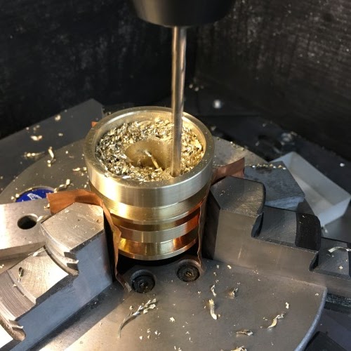
The lathe work done, the part is put on the mill to drill the mounting holes on the top side. The copper foil is to prevent the steel chuck jaws from marring the hard-won surface finish of the flanges.

... and the pressure vents on the bottom. Having said NO mistakes, I then made one here. If you look carefully, you can see a seventh centre-drill mark where I drew an extra point for construction in the CAM file and forgot to erase it. Fortunately, this is just cosmetic as it doesn't pass through the flange.

A better shot of the vents.

Here is the collection of the parts for the assembly: the piston rod plus floating head, the piston head, three stainless machine screws and washers and an 8mm dowel pin (more on this last part another day). The little red arrow shows the relief groove that the washers will fit into to keep the head in place.

A close up of the connection detail with the washer in place.

And, the free-to-wiggle result!

Tons of progress over the last few weeks. I have lots to report, but the first post of 2018 is the last part of the piston build which I started before the holiday.
Unlike the other parts of the piston assembly, the head is a wetted surface and consequently needs to be made from a lead-free material. I bought some 2" diameter C69000 quite a long time ago for this purpose, but it has taken a while to get to it. Partly, this is because this stuff is expensive (even for brass). I also have to get it from the states, which is a huge added expense and hassle. SO: no mistakes!
The rough diameter is pretty close to the diameter of the piston so I have to chuck the stock carefully to avoid excessive run-out. Unfortunately, it is too large for the internal bore of my trusty 6-jaw so I have to use the 4-jaw annoyance.

Remove a little material to get close to the desired piston diameter (close in this case is within 0.001"). Then the last thousandth is removed with a sanding block and a succession of grits (from 400 all the way to 2000). This puts the P in precision as far as my shop is concerned.

Then we add the seal and relief grooves.


Once the grooves are finished, the internal bores at the top end are added.


And, after chamfering all the sharp edges, the piston head can be cut off from the stock.

The lathe work done, the part is put on the mill to drill the mounting holes on the top side. The copper foil is to prevent the steel chuck jaws from marring the hard-won surface finish of the flanges.
... and the pressure vents on the bottom. Having said NO mistakes, I then made one here. If you look carefully, you can see a seventh centre-drill mark where I drew an extra point for construction in the CAM file and forgot to erase it. Fortunately, this is just cosmetic as it doesn't pass through the flange.

A better shot of the vents.


A close up of the connection detail with the washer in place.

And, the free-to-wiggle result!

No comments:
Post a Comment