Showing posts with label Boiler. Show all posts

Wednesday, 17 January 2018

Brew reservoir

Today's installment is the first foundry production part: the brew reservoir. I made the prototype entirely from discrete stainless parts, but the complex form means that it is much more efficient to make a casting.

The prototype reservoir from 2016.


Image


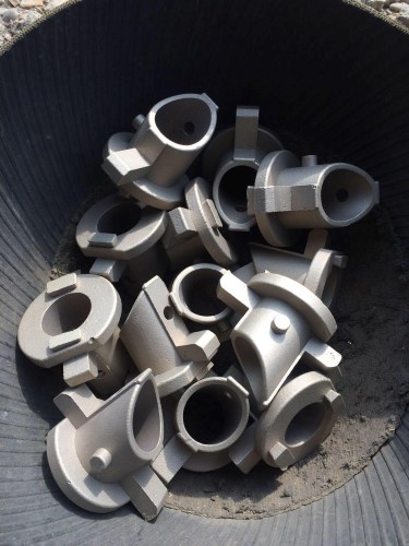
After a lengthy exchange with the foundry: one bucket-o-castings! Slightly more costly than KFC.


The rectangular blocks on the face of the flange are casting "risers" that provide a reservoir of liquid metal that is drawn into the casting as it solidifies to prevent internal voids from forming. 


The large void in the surface means that this one is likely a reject and will go back into the melting pot.


A few days later and the parts arrived at my shop. So easy!


As the foundry molds have to be made anyway, I thought I may as well add the detail of the threaded nub on the side of the reservoir. This is an easy place to unobtrusively attach a thermocouple - the data from which may or may not be useful. Time will tell.

Sunday, 6 November 2016

Concluding the day's posts: I needed to make a couple of 1" BSPP (G-thread) x 3/4" copper sweat adaptors that will form the ends of the heat exchanger tube and make the seal with the boiler plate. These are necessarily custom parts as this they adapt from European to North American standards. However, I think that is it reasonable to consider the HX tube as a non-serviceable i.e. a custom part.

Lead-free hex stock after threading, chamfering and cut-off operations.


View from the other side showing the 90 degree included-angle internal chamfer that will seat and seal with the hemispherical "bi-cone" fitting.


The part is flipped and bored to receive the 3/4 copper pipe.


Test fit of the pipe.


Sunday, 23 October 2016

Boiler part 7 - pressure testing

Pressure test day!

All of the plugs are cut and fit to the boiler with a little Teflon tape.


The pickling paste cleaned the stainless welds nicely by removing the surface layer of metal that was oxidized during the welding and brazing.


The 1/4" ply wood blank end started leaking at about 10 psi. I must not have had enough coffee - don't know what I was thinking.


Same blank plate, this time made from a scrap of unidentified aluminum (from Nortel!).


Using a regulator, a manual valve and a check-valve I can up the pressure gradually and keep it there for a bubble test in the sink. 54 psi on the dial - which is 3.75 times the working pressure and more than twice the maximum pressure (the safety valve opens at 1.5 bar). I will not be pressure testing all the way to failure  ;-)

The boiler is done!


Boiler part 6 - BSPP plugs

Before I can pressure test the boiler I need to plug all of the holes!
I ordered a couple of cheapee G-thread dies a couple of months ago, but didn't consider the problem of holding them. They are, very conveniently, different diameters. So I decided that it was finally time to build a die holding system for the lathe. A mild steel handle, some 2" OD aluminum tubing, an acetal hub with a stainless shank and, in the case of the larger diameter die, a 6061 aluminum adaptor.


Once done, cranking out the 1/4 and 3/8 plugs in acetal was a snap. Then I dropped them into the milling machine to cut some shoulders for wrenching. I love working with acetal - you can almost form it by staring at it hard.   


Boiler part 5 - final weld-up

Welding time!

First thing that is required is a stand; made from a couple of scraps of 1x1 mild steel tubing and a piece of L section.


The tube rotates easily in the stand which makes it simple to keep the torch and filler material alignment correct. 


I experimented a bit beforehand using some scraps of the same materials and decided that a fairly agressive butt-weld seemed to offer the best weld consistency. Close-up of the finished weld. 


Lead-free brass parts brazed in place.


A view of the open end. I should probably have fluxed the inside of the tube more than I did to prevent the oxidation.


The lone fitting in the centre of the boiler tube is the brass thermal bridge that will sit inside the brew reservoir to facilitate the heat-transfer.


Last bit of welding it the most tricky as space it tight and the pipe wall thicknesses differ: connecting the brew reservoir to the boiler tube. The boiler is now done except for cleanup with pickling paste. This last task was significantly less fun as handling hydrofluoric acid is not exactly like playing with a bundle of puppies. 


Boiler part 4 - inlets and outlets

Ok - boiler build time!

The second attempt at the boiler bolt ring using 304 stainless M10 set screws. The previous attempt (no picture at the moment) involved brazing socket head cap screws in place. This proved problematic: I ran out of gas (not once, but twice) while attempting to braze them in place with a toy oxy-acetylene torch from the hardware store. I then attempted to finish the brazing using my TIG torch as heat source - which, while technically possible, was, in the hands of this welder, not a good idea. Lot of swearing that day.  :o  Since then, I have finally succumbed and added a real oxy-acetylene setup to the shop.


The biggest problem with cutting the holes in the boiler was holding the 6" diameter pipe in the mill. I finally decided to tack weld the ends in place to give the pipe itself enough rigidity during machining. 


Even having done this, I couldn't get enough clamping pressure and holding force (without spending a day or two on building a jig) to prevent the whole part from lifting when cutting the holes with an end mill. So dumb drilling it had to be. First a centre-drill.


Then I work my way up through drill bits by about a 1/16" at a time...


...till I get to 3/4". I would have built a jig, but I think that I may well be able to have the boiler tube pre-cut with on a laser tube cutter, so I will hold off until I have a better understanding of the requirements.


Image of the holding setup. It was enough to keep the assembly from moving laterally, but didn't generate enough friction from stopping the boiler from lifting when using the end mill...


First row of holes complete and I use a pointed brass spud for a visual alignment of the next bunch. The lead-free fittings that I cut on the lathe are dry-fit for now. I like to mark out the placement with a Sharpie by hand before drilling to avoid the painful forehead slap on the discovery that the part was placed backwards in the vice and consequently the holes are in the wrong place. 


A little cleanup with a deburring tool and we are done! 


Friday, 2 September 2016

Boiler part 3 - brew reservoir weldup

Everything seems slower in August. The weather is good, the city has a relaxed atmosphere and somehow, sitting indoors in front of the computer is less attractive than it is in February. I do have some progress to report however. First, the brew reservoir is pretty close to completion. I tack welded on a couple of pretty hefty lugs that will carry the whole load of the boiler when it is attached to the frame. Then I brazed the G1/4" fitting in place. The fitting, by the way, was cut and tapped on the lathe from lead-free Ecobrass hex stock - which, though a little more difficult to machine than leaded brass, turns out to be pretty good. I have done quite a bit of soldering in the past but never any silver brazing - so I was exited to see how this would work. The white gunk in the before shot is flux which prevents atmospheric oxygen reaching the metals in the joint and oxidizing them as they are heated. Using an oxy-acetylene torch, the base part is heated evenly until the assembly reaches the melting point of the brazing metal (~1145 to 1650°F (618 to 899°C) depending on the brazing alloy). Just like with soldering, once the right temperature is reached, the liquified braze is drawn into the joint by capillary action. The hard part is actually to not overheat the joint - the oxy torch is a powerful beast - that and the cleanup afterwards which is a royal pita. This part just needs the final structural welds on the lugs and then it can be welded to the boiler tube.


Boiler part 2 - boiler tube

So, on to the boiler tube!

This is a piece of 6" schedule 40 316 stainless pipe. It looks quite innocent and happy on the lathe in the picture. Cutting it, however, was not so easy! It is held at one end nicely by the six-jaw chuck from the inside. The other end, however, is completely unsupported. As it isn't even sort of round, it can't be clamped externally, so the only way to hold it is with an elaborate internal expanding plug - which would take a day or so to make. As this is a part which will likely be laser cut when I need more of them, I didn't want to go there. So, with the lathe on dead-slow and taking extremely light cuts (0.001" per revolution) with a carbide parting tool I cut it unsupported. As the setup is not even sort of rigid, the tool tends to chatter a bit, which has the effect of resonating and ringing the tube like a bell. REALLY LOUD! Even with heavy ear protection, I could feel my back teeth buzzing. Still, it did a good job and the end result is a very clean edge about as perpendicular to the walls as you can get.


Sunday, 31 July 2016

Boiler part 1 - brew reservoir

Over the last few weeks, along with spinning a few other plates, I sent out for some stainless parts for the boiler. I decided to go with an all stainless construction because, even though it is more expensive than copper alloys, it is far simpler to get the parts made. A copper and brass assembly would have required at least one, possible as many as three separate castings, plus a whole lot of hand fabrication; expensive and time consuming. The laser-cut stainless parts were delivered in seven days after I placed the order.


Clockwise from the top right - the flange to connect the group to the boiler, the boiler flange, bolt circle flange and the fixed end flange.

First the group flange has to be drilled out to the correct minor diameter and then tapped. Starting with the tap held in the drill press to make sure it goes in straight and then finishing by hand. 


The brew reservoir that sits behind the group flange to provide preheated water for the chamber is made from a small section of schedule 40 stainless pipe. The square end is cleaned up on the mill and then a radius is added to the opposite end which is rough cut at a 30 degree angle.


Then we fire up the tig welder to put a structural fillet on the outside of the joint and surface butt-weld to seal the inside. Welding, I am convinced, is good for the soul. A little buffing with a wire brush and the part is ready to receive the lugs than will hold it to the frame. Then the assembly can be welded onto the boiler tube. I also realize, while writing this, that I am missing a hole in the wall of the reservoir tube to provide an inlet for the water from the HX. 😶   It wont be terribly useful without that.