After my slight misadventure with the cam, it became clear to me that there comes a time in everyone's life (ok, maybe not everyone), when it is time to build a press. Today's post is about turning this into that.
The "this" in this case are mostly parts that I took out of my mill when I was converting it to CNC.

The two key ingredients here are the thrust bearing (for transferring axial load)...

...and the trapezoidal thread lead screw. I'm also going to reuse the giant bushing (with the blue paint on it). The bearing and the bushing were used to move the head of the mill (which weighs about 250lbs) up and down the column, so they are hefty enough for the job I want them for.

The bearing used to sit inside the bushing at the top of the mill column with the weight of the head (and the 1HP motor) hanging on it, so the first job is to flip the bushing around so that it can be used to push instead of pull.

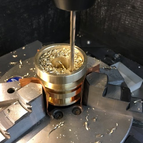
There are a pair of perpendicular tapered dowel pins holding the steel bearing seat to the end of the lead screw, one of which I am reusing to hold a new brass nut (I also cut off part of the end of the lead screw journal to provide space for the nut).

The plastic spacer sits at the bottom of the hole in the bushing and draws the bearing seat and the bearing tight to the back.

The business end!

Now we make a series of holes in a piece of 1" steel pipe (which is painted and looks suspiciously like it may have come from a pipe clamp, which is odd because I don't have any pipe clamps, so sorry to whoever it was that lent it to me, you can't have it back now)...


...and weld on a couple of threaded end caps.


Now it is time for the base, which is a square piece of 5/16" mild steel plate.

The crossbar is made from some super-duper 2" stainless square tubing...

... which is drilled to receive the outside diameter of the tubing at the extremities and the lead screw in the middle.

Then I flip the tube and cross-drill for the 1/2" pins that will hold the crossbar.

The lead nut that used to attached the head of the mill to the screw is an exceedingly rough iron casting. My disgust with the quality was such that I didn't take photos of the "before", before I cleaned it up to fit inside the crossbar.

Now it fits nicely inside the square tubing.

The finished frame.

Then I cut the screw in half because it is way too long as is. Definitely no going back now.


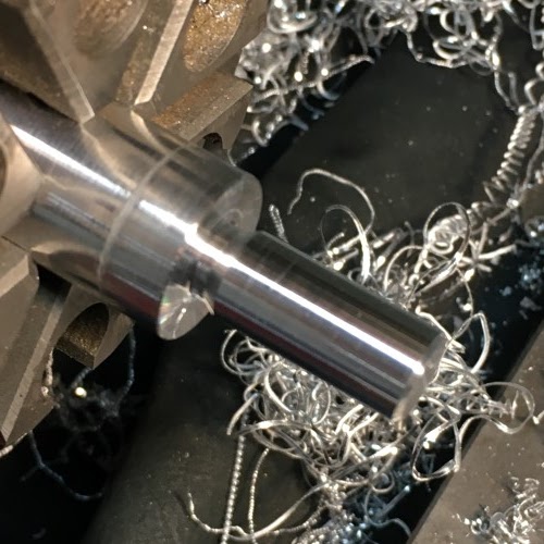
Add a new journal to the cut end...

...cut a flat...

...and put one of the old manual control wheels from the mill table on the end.

I made a quick adapter for the cam bracket and (messy work space aside)...

...we have achieved 100% compression.

The "this" in this case are mostly parts that I took out of my mill when I was converting it to CNC.

The two key ingredients here are the thrust bearing (for transferring axial load)...

...and the trapezoidal thread lead screw. I'm also going to reuse the giant bushing (with the blue paint on it). The bearing and the bushing were used to move the head of the mill (which weighs about 250lbs) up and down the column, so they are hefty enough for the job I want them for.

The bearing used to sit inside the bushing at the top of the mill column with the weight of the head (and the 1HP motor) hanging on it, so the first job is to flip the bushing around so that it can be used to push instead of pull.

There are a pair of perpendicular tapered dowel pins holding the steel bearing seat to the end of the lead screw, one of which I am reusing to hold a new brass nut (I also cut off part of the end of the lead screw journal to provide space for the nut).

The plastic spacer sits at the bottom of the hole in the bushing and draws the bearing seat and the bearing tight to the back.

The business end!

Now we make a series of holes in a piece of 1" steel pipe (which is painted and looks suspiciously like it may have come from a pipe clamp, which is odd because I don't have any pipe clamps, so sorry to whoever it was that lent it to me, you can't have it back now)...


...and weld on a couple of threaded end caps.


Now it is time for the base, which is a square piece of 5/16" mild steel plate.

The crossbar is made from some super-duper 2" stainless square tubing...

... which is drilled to receive the outside diameter of the tubing at the extremities and the lead screw in the middle.

Then I flip the tube and cross-drill for the 1/2" pins that will hold the crossbar.

The lead nut that used to attached the head of the mill to the screw is an exceedingly rough iron casting. My disgust with the quality was such that I didn't take photos of the "before", before I cleaned it up to fit inside the crossbar.

Now it fits nicely inside the square tubing.

The finished frame.

Then I cut the screw in half because it is way too long as is. Definitely no going back now.


Add a new journal to the cut end...

...cut a flat...

...and put one of the old manual control wheels from the mill table on the end.

I made a quick adapter for the cam bracket and (messy work space aside)...

...we have achieved 100% compression.