Monday 25 December 2017

Piston assembly part 5 - aluminum beds

Part two of this holiday build is the piston rod arm. Thanks to this part I now have a new favorite material: Aluminum 7075 - this stuff is awesome! Extensively used in aviation, it has similar mechanical properties to steel but obviously doesn't rust. It is easy to machine and the chips are non-magnetic (so they don't stick to the rare-earth magnets I use for holding chip shields etc in place). I just love this stuff. I think I'm gonna build my next house out of it - walls, floors, beds ... everything!

The blank is cut on the cold saw - the band saw takes too long with this stuff. 


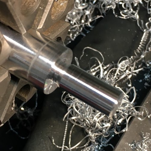
Then it is turned down to the right diameter.


Then I turn down a stub to the major diameter of M10 (i.e. 10mm - got to love the metric thread system!) and add a thread relief groove at the shoulder.


Thread the stub with an M10x1.5mm die.


Cross-drill the other end of the arm for the the 8mm pin...


... and test the fit.


The finished piston arm assembly.


Sunday 24 December 2017

Piston assembly part 4 - aspirational wobble

Holiday special post!

After spending quite a while thinking about how and whether to re-engineer the piston I finally decided to duplicate an older Aurora assembly shown to me by Dr. Pootoogoo, famed baristorian. This design allows the piston head to "float" and self-align to the cylinder bore and compensating for any machining error (the so-called axial alignment problem that I identified with the first prototype of the group body casting a number of months ago). Although it obviously slightly more complicated than a fixed piston (extra parts and assembly) it will resolve any alignment errors that may be present in the first run of production castings. Additionally, swapping to the fixed piston design will be easy as the piston head itself will be machined from the same rough casting or stock.


Starting from a piece of 2" C360 brass:


Then I add a couple of angled cuts to the tip to approximate a radius - this is quicker to setup than cutting an actual arc and makes no difference to functionality.


Then, using a cut-off/grooving tool I add an undercut below what will be the flange.


Another groove is cut above the flange to create the boss that will align the spring.


Then the part is cut-off from the stock...


... and flipped around to be drilled...


... and tapped with an M10 thread.


After that I move the part to the mill and centre it with a probe.


Three clearing holes are drilled in the flange and boss.


To be continued!

Wednesday 13 December 2017

Rain forest part 6 - wood blanks

Wood blanks going through the same workflow at the foam parts.

First roughing step down.


Quite a long time later ...


A little sanding, some oil and with the brass inserts glued in place, these are done.


Piston assembly part 3 - VW rings

I've looked into the piston design in some detail now but I'm undecided as to how to proceed. I suspect you are correct in assuming that a plain o-ring will work just fine for the thousand-cycle per year range of home use. After all, the V & W seals on my home machine have been replaced maybe twice in twenty years. Silicon o-rings would likely be more prone to spiral failure as the original piston is not designed with the softer material in mind. I had decided to try out a drop-in replacement piston design using off the shelf silicon quad rings but unfortunately, the 50mm bore of the classic Aurora group does not play well with AS568 (aka inch sized) o-rings. 50mm sits at an awkward spot between inch sizes which will mean either too much squeeze (compression of the ring's cross section) or too much stretch (elongation of the circumference). The correct metric size quad ring does exist, but I haven't found a supplier yet. This is compounded by the material requirement: silicon is rare, FDA approved silicon even more rare. In short: for now it's back to Faema V and W rings.

On the build front, I am anxiously waiting for another shipment of parts which has been held up because a few minor bits were back-ordered.

When it arrives, I should be in possession of every single part required to complete the very first machine (finally, yessssssssss)! Maybe in time for Christmas....

I have been busy with supplier negotiations for the last while and I don't have too much concrete to show.


I did put two wood blanks through the process for making the handles:


...quite a long time later:


These just need some oil.

Piston assembly part 2 - pondering rings

Thanks to HB's Bluecold for the reference to Erik's technical o-ring manual.

The answer to my question is found within:

"Spiral failure sometimes occurs on reciprocating O-rings.

The conditions which cause this type of failure are those which cause segments of the O- ring to slide and other segments to roll simultaneously. The twisted seal is forced by the pressure into the sharp corner at the clearance gap. Rapid stress-aging can cause a rupture of the O-ring to start adjacent to the clearance gap. Motion of the O-ring causes the rupture to penetrate about half way through the cross section. Thus, when the O-ring is removed from the gland, it returns to its original shape and the rupture appears as a tight spiral around the cross section. One of the primary causes of spiral failure is by reciprocating speeds of less than one foot (0,3 m) per minute and on low or balanced pressure components. At this low speed, the sliding, or running, seal friction is very high relative to the break-out friction.

Therefore O-ring seals are not recommended for speeds less than 1 foot (0,3 m) per minute when the pressure difference is less than 400 psi (27,5 bar)."


Of course, it's possible that o-rings will work just fine, but perhaps may fail earlier.

Tuesday 14 November 2017

Piston assembly part 1 - trained seals

So, I have been wondering about seals.

Image

Ok, not that kind. I've been thinking about the seal setup for the aurora and comparing it with some other solutions. The aurora uses two different W and V seals that are currently made by Faema.


Cafelat make a nice silicon version of the V seal, but I guess there isn't enough demand for the W. I am not worried about being able to find parts (there are plenty, plenty machines out there that need the W seal). But I was fooling around with a Flair, a completely manual lever, and it set me wondering: why this seal setup in the first place? What advantage, if any, is there of this type of seal over the much more common o-ring? After all, o-rings are completely ubiquitous in hydraulic and pneumatic cylinders with pressures a least a couple of orders of magnitude greater than the ten bar range.

This is a setup from a smaller-bored lever, I don't remember which.


Friday 10 November 2017

Rain forest part 5 - adventures in foam

The smart way to fabricate the valve handles is to make them out of plastic using an injection-molding machine (actually, the smart way is just to buy them, but anyhow). However, as we don't necessarily do things the "smart" way around here and wood is rather difficult to melt, that method has been ruled out. Consequently, there are quite a few machining steps that have to gone through in order to make these individually. Getting the order of operations right is important because we might find ourselves 'machined into a corner' and unable to hold the parts before they are completed.

Starting with the foam blank cut to finished length in the lathe, I bored out the front and back interior profiles.


The front:


and the back:


Now, I want to put an outside taper on the back while the stock is still in the lathe. This is problematic as I will no longer be able to hold the back of the part in a chuck after I cut the taper. This calls for a stub or jig that fits the interior profile of the stock.

Drill and tap a hole in some aluminum round bar:


and then machine the tapped end to the correct diameter.


Now I can cut the taper.


All the operations on the lathe are done and I can move the part, securely fastened to the stub, over to the mill.


The milling program roughs out a perimeter to a certain depth and then refines the shape moving back upwards before stepping down to the next roughing level. The white rubber keeps the dust (mostly) within the range of the vacuum.


...down to the fourth roughing level.


... a few levels more and then I can take the part off the mill.


The threaded brass insert from the valve fits snugly in the foam version and will be glued in place for the finished parts.


I (heart) foam.


Sunday 29 October 2017

Rain forest part 4 - all cylinders

Today on the bidoowee channel: we are making cylinders!

I was holding back from tackling the handles for the steam and h.w. in the hopes that I could find something off the shelf. I've been looking for months and I have a number of candidates, but there are problems or complexities with them all so I am admitting defeat and making them out of tree. I wasn't particularly happy about having both wood and plastic in the design in any case, so there is an upside.

All that to say, we are not out of the woods yet ;-)

I cut another section out of leftover lumber and ripped it into two squares profiles.


Then I knocked the corners off to get closer to the final shape. 


Then I put the dreaded four jaw chuck on the lathe. I hate these things - what a pita: use a dial gauge to measure one side of the stock. Rotate the workpiece 180 degrees without upsetting the gauge, measure again. Move the stock by adjusting the jaws by half of the offset between the opposite sides. Repeat until it is correct or you get bored. Then do it again for the other two opposing sides. Tighten everything down, then readjust because the stock is soft. Requires the patience of saints.


I did some fairly careful planning for cutting these parts because they are reasonably complicated. I figured that I can get all the pieces out of two 29 1/4" lengths. The octagons just fit between the chuck and the tailstock of the lathe and, with about 1/8" to spare between the thread chasing dial (which I thankfully no longer have to use 'cause CNC is the just the bees' knees for threading thank you very much) and the pillow block, there is enough travel to machine the entire length. 


The setup for the machining requires good dust extraction to keep all the crap from getting onto the ways and into the screws. A metal lathe is really not the correct tool for this job, but I don't have an alternative. So, I found a high tech solution: elastic bands and bailing wire to hold the vacuum nozzle in place and scrap of plexi held with a magnet.


A number of passes were required, but the carbide bit is fairly sharp and leaves a reasonable finish on the wood. 


I also made a blank out of foam so that I have an expendable test piece that wont break any tooling during the next phase of machining.


Result? Two wooden dowels and a foam blank. Total excitement.