Thursday, 25 February 2016

Building a lever machine... from scratch

One particularly cold February morning, I got up to discover that the auto-fill circuit on my Brugnetti Aurora had failed. As I opened up the Gicar controller a few days-without-proper-morning-coffee later to figure out what was wrong (an old and faded capacitor), I realized that I had now either fixed or maintained every system on the machine except the lever group. So I took that apart too and replaced the spring and the gaskets. As I was putting it back together I started wondering about what it would take, given that the original Brugnetti company no longer exists, to make more of these fantastic machines.


A few days ago, after nearly three months of research, drawing, discussion and negotiation, I received these photos:


... a wax positive of the group body which, over the next few days, is going to be encased in plaster and replaced with molten brass.

The photos are also a sign, at least to me, that this project is now well and truly underway and that it is time to share it with the generous people on this forum, whose advice I have greatly benefited from since my obsession with coffee began. I am a long, long way from a working machine, but you have to start somewhere.

Contemplating building a lever group - that way madness lies

The Brugnetti Aurora is my favorite single group vintage espresso machine: minimalist design, bold colors and a fantastic logo in a cousin of the 1962 Eurostyle font. The one in the picture, an HX version, was restored by Orphan Espresso. It was likely assembled and sold in the US by Termozona, an importer from Connecticut who added, what is in my opinion, the criminally design-inappropriate Europa badge on the front.  


Everyone who I have spoken to agrees that they are great machines: simple, well built, small enough for home use, and above all else, capable of producing an incredible shot of espresso. They are, however, rare. The original Sr. Brugnetti closed down and liquidated his factory before the brand was relaunched under new management after a five year hiatus. Brugnetti no longer makes lever machines and I presume that the original group head molds, manufactured by them or a supplier (Tortorelli Meccanica in Sienna?), either no longer exist or would be impossible to track down with my hundred words of Italian.


The heart of the matter is the lever group and the heart of the group is the group body which is a complicated part. So the million dollar question is what would it take to reproduce it?

No, I will weep no more. In such a night
To shut me out? Pour on; I will endure.
In such a night as this? O Regan, Goneril!
Your old kind father, whose frank heart gave all—
O, that way madness lies; let me shun that;
No more of that.


King Lear Act 3, scene 4, 17–22


References

A discussion of building a lever machine from scratch with reference to the aurora. thread discussing the origins, shrouded in myth, of the machine.
Another couple of restorations of the European Aurora from kaffee-netz in Germany are here and here.
A restoration of a two group model - surely not an original case?

Friday, 19 February 2016

Repost of Orphan Espresso's restoration of the Aurora

(Doug's images links were broken. So I repost them here.) bidoowee

The Aurora Europa, AKA Termozona is one of the few true heat exchange single group espresso machines from the vintage era.  This particular machine is from the 1970's.   I say single group since many of the different machine manufacturers  used a dipper feed for the single groups and HX for the multiple group machines, but the Aurora is a true single group HX with a large boiler and small footprint.  I have been told that Brungnetti made all or at least most of their components "in house" and this shows in the Europa, since most of the components are unique to the Aurora machines, with not a lot of interchange from or to other machine makes.  


The boiler is large and I have modified the layout a bit by removing the autofill system (I think it is not needed in a home application and adds to the complexity of long term use/maintenance).   The blind cap on the end plate closes the autofill fitting and instead of the probe on the top of the boiler I added a vac valve to make warmup a simple and rapid event.  Below you can follow th HX water route quite clearly...fresh water from the water line enters the HX through the large fitting on the left of the end plate and exits through the other large fitting on the right.   A pipe goes directly to the top of the group and fills a space in the neck behind the group.   The water in this space brews the shot.  The HX tube is about 1" diameter copper pipe.


The machine is 110volt as original.


Full size 30 amp Sirai pstat mounts under the boiler and is pressure fed by a pipe from the bottom of the water level sight glass housing.


This view shows that all of the piping comes from the boiler plate side.  The boiler is suspended by the pipes and the group to boiler flange.


Special attention has been paid to the top lever/fulcrum mechanism with the bearings tightly encased in a cast frame.  The bearings roll on replaceable shoes and are held in alignment with adjustable side plates.   The piston is removed by threading out the slot head screws below the lever bearing housings.


Very simple front work area with manometer indicating a .7 to .9 bar sweet spot for pstat adjustment.   The wands can be made to swivel but are generally fixed in postition.  The drip tray is held in place by a spring clip mechanism.


Under the tray is the drain sump and the water inlet valve.  The rear port of the valve feeds the HX tube and is always on and the front port of the valve corresponds to the manual boiler fill and is controlled by the side exit handle.  The overpressure valve that empties into the sump is fed by a side branch from the HX line.   This would function as a pressure limiter on the water line but it is better to use a stand alone line valve for this.   The HX pressure regulator shown here is more or less a safety feature and as I have it set up does not function well to regulate HX line pressure.


The heating element and HX loop inside the boiler are built almost right into one another.


And the HX tube is directly above the heating element.


Another view of the heart if not soul of this system.


The spring on the Aurora is possibly the strongest I have encountered, which means that it was VERY difficult to install.   Compression of the spring was 100% at the point I was able to insert the upper rod pin.  This view is of a new spring and clean piston with new seals.


The face of the piston has large pressurizing holes to keep the seal tight against the cylinder walls.   The piston uses the same V and W seal system as found in the classic Faema groups.  


These are some of the salient features of the Aurora Europa save the case.    In general the machine is simple and overall not bad to work on....there are some order counts issues in assembling the frame components at the sight glass and electrical switch panels.   The sight glass parts come out as a unit, but the sheet metal must be removed first...not as convenient as some.  The HX is a very nice system on these machines since one can both heat and cool the group at will and pulling shots does not deplete the boiler....one can pull a shot and steam at the same time of course, and this is part of the point of this type of system.   


Friday, 22 January 2016

Miata aftermarket alarm system uninstall

Gathering information for taking out the aftermarket alarm which is draining the battery with a dark current of about 50ma...


Wiring diagrams for the 2000 nb
http://neomiata.com/garage/index.php?path=Wiring+Diagrams/


Wire list used by alarm installers for 2000 miata
http://alarmsellout.com/support/diagrams/vehicle/MAZDA%20MIATA%201990-2005.pdf


WIRE
COLOR
LOCATION
12V CONSTANT WIRE
WHITE/RED
Ignition Harness
STARTER WIRE
WHITE/BLACK
Ignition Harness
12V IGNITION WIRE
RED/BLACK
Ignition Harness
SECOND 12V IGNITION WIRE
BLACK/RED
Ignition Harness
12V ACCESSORY WIRE
GREEN/RED
Ignition Harness
POWER DOOR LOCK
Must add actuator in doors
POWER DOOR UNLOCK
Must add actuator in doors
PARKING LIGHTS (+)
RED/BLACK
Rear Of Dimmer Switch
PARKING LIGHTS (-)
LT.GREEN
Harness At Steering Column
DOOR TRIGGER/DOME LIGHT SUPERVISION (-)
WHITE/RED 
Harness In Driver’s Kick Panel
TACHOMETER
BROWN or BROWN/YELLOW
Ignition Coil
BRAKE WIRE (+)
GREEN
At Brake Pedal Switch
HORN TRIGGER (-)
GREEN/ORANGE
Harness At Steering Column
LEFT FRONT WINDOW UP
GREEN/RED
In Center Console
LEFT FRONT WINDOW DOWN
WHITE/RED
In Center Console
RIGHT FRONT WINDOW UP
RED/BLACK
In Center Console
RIGHT FRONT WINDOW DOWN
RED/GREEN
In Center Console


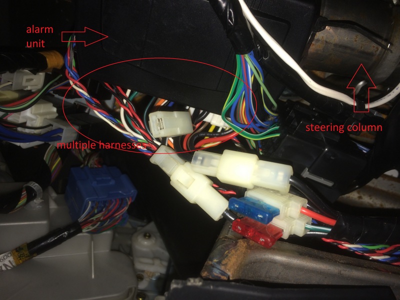
... And here is the offending 20mA brainstem parasite. One relay on the ignition starter wire, power drawn from the 12v constant wire for the control module and the siren, and multiple harnesses to the door trigger, a mercury switch in the trunk, a contact in the hood, a led in the console and to the headlight relay. Good riddance!


Monday, 23 November 2015

Houston, we have ignition. Mazda Miata

The NA and NB Mazda Miata are fine examples of KISS (Keep It Simple Stupid) engineering. One corner I feel was a cut too far is the omission of an ignition key light. You just can't see where the key goes on a dark night or in an underground car park. Given the simplicity of this creature comfort, it doesn't seem like it should be too much to ask. A quick hunt on the excellent www.miata.net forum turned up a Brian Weltman's circuit and instructions.

Circuit

I happened to have equivalents to everything in Brian's Radio Shack bill of materials on hand. I ran into a little trouble however, with his design. The feed to the relay coil (the red/black) comes from a 12v source in the ignition circuit. For whatever reason, the reading in my car from that source to ground was closer to 14.5v. Given the heavy gauge of the red/blk wire (approximately 12AWG) I suspect that it is carrying a fair amount of current. The over voltage, coupled, I presume, with the high current, burnt out the relay coil on the first try. No relay coil means the LED wont turn off immediately when you start ignition. 


Replacing the relay with one that has a higher coil voltage would be one way of resolving this. However, I didn't have one on hand. Also, while I am not an electrical engineer, I am not convinced that it is a good idea to leave what amounts to a direct short via the coil to ground open while you have the ignition on. I therefore added an LM317 voltage regulator to the coil side of the circuit. This serves the dual purpose of dropping the voltage the coil sees down to 11.5v and limiting the current that passes through the circuit to ground.


The red/blk wire from the ignition feeds the V_in side of the circuit. V_out is sent to one side of the coil. Values used for components were:

C_in = 10uF (rated to 25v)
R1 = 270 ohm
R2 = 2.2K ohm
C_out = 1uF (16v)

Given the very small current requirement of the coil and the simplicity of the circuit, I suspect that the input and output filter capacitors are probably not necessary, but we are going with belt and suspenders today.

  Finished circuit.


As I had to cut the wires to fix the relay problem I added molex connectors so that the whole shebang can be removed or replaced.


EDIT - 2017 2 3

Complete parts list:

2 x 2.2k ohm resistor
1 x 275 ohm resistor
1 x 120 ohm resistor
1 x white led
1 x 1N4004 diode
1 x 1uf capacitor
1 x 0.1uf capacitor
1 x 4700uf capacitor
1 x LM317 regulator
1 x PRMA1A12 relay
1 x proto board
6 x 18" wire
shrink wrap
tie wraps
wire taps optional


Relay pinout


LM317 circuit and pinout


_______________________________________________________________

Wire connection points

I can confirm that the wires are indeed exceeding awkward to get to without removing the driver's seat, but, by lying on your back on the seat with your head in the pedals it can be done. The light gauge (approximately 22AWG) blue/red & white/red wires that feed the dome light in my 2000 NB were aft, above and to the left of the dead pedal. They were held by a clip in the door frame above the hood release catch. [From what I understand, there is no dome light on earlier models so you will have to find another source of 12v that is activated by the door switch.]


The arrow pointing up indicates the hood release cable.
The arrow pointing left is where I attached my splice connectors.
Note - my NB has an (annoying) alarm/immobilizer that was previously spliced into the same place (the brown wire).


The heavier gauge (~12AWG) red with black stripe wire follows the steering column. It is immediately visible on the left side of the column close to the steering wheel once the plastic clam shell cover and the rectangular piece below it are removed as per Brian's instructions. 


Installation 

I ran into a further minor complication here as the finished circuit board is slightly too large to fit against the other components near the ignition in the position I had intended. I just flipped it around and tie-wrapped it to the wiring harness a little below the clam shell.


Sunday, 21 June 2015

Mach3 compatible Motion controllers - for when the parallel port finally dies

CNCdrive

http://cncdrive.com/MC/UC300%20datasheet/UC300%20users%20guide.pdf

http://cncdrive.com/UC100.html

what the people are saying:
http://www.machsupport.com/forum/index.php?topic=25448.0http://www.machsupport.com/forum/index.php?topic=25448.0


Friday, 3 April 2015