Sunday, 31 July 2016

Boiler part 1 - brew reservoir

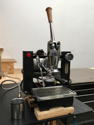
Over the last few weeks, along with spinning a few other plates, I sent out for some stainless parts for the boiler. I decided to go with an all stainless construction because, even though it is more expensive than copper alloys, it is far simpler to get the parts made. A copper and brass assembly would have required at least one, possible as many as three separate castings, plus a whole lot of hand fabrication; expensive and time consuming. The laser-cut stainless parts were delivered in seven days after I placed the order.


Clockwise from the top right - the flange to connect the group to the boiler, the boiler flange, bolt circle flange and the fixed end flange.

First the group flange has to be drilled out to the correct minor diameter and then tapped. Starting with the tap held in the drill press to make sure it goes in straight and then finishing by hand. 


The brew reservoir that sits behind the group flange to provide preheated water for the chamber is made from a small section of schedule 40 stainless pipe. The square end is cleaned up on the mill and then a radius is added to the opposite end which is rough cut at a 30 degree angle.


Then we fire up the tig welder to put a structural fillet on the outside of the joint and surface butt-weld to seal the inside. Welding, I am convinced, is good for the soul. A little buffing with a wire brush and the part is ready to receive the lugs than will hold it to the frame. Then the assembly can be welded onto the boiler tube. I also realize, while writing this, that I am missing a hole in the wall of the reservoir tube to provide an inlet for the water from the HX. 😶   It wont be terribly useful without that.


Monday, 4 July 2016

Test of the group body prototype


At the end of last week I received the prototype of the group body from the foundry. There was a little confusion with the shipping and the package got left on the doorstep of my office overnight! Very fortunately, despite spending the night on a busy street, it was still there the next morning. I have taken quite a few measurements and, although there are a couple of small problems, I am very pleased with the result. I put the new body into my stripped-down machine with the rest of the original group parts to limit the scope of the testing. The first results were a little worrying: even after a good warm-up, there was a constant flow of water past the lower piston seal. I took a closer look at the piston and decided to replace both seals, which, though they were working fine in the old group, are a couple of years old. Success - no more water past the seal. My suspicion, though I haven't tried to measure this yet, is that there is a certain amount of error in the alignment of the cylinder bore with respect to the top of the group. If the axis of the bore isn't perpendicular to the surface that the rest of the group parts are bolted to it will mean that the axis of the piston wont be parallel with the axis of cylinder. It also makes sense that a pair of cylinder and piston parts that have lived together for decades would generate a unique wear pattern on the seals. I may also add a PTFE (Teflon) guide ring to the piston which will greatly increase the concentricity of the piston with respect to the cylinder.

Finding a good fit for the portafilter seal was another small adventure. The groove for the seal has a couple of out-of-tolerance dimensions which will have to be addressed in the next production run. This means that there is less space (both axially and radially) than is needed for the generic 73mm x 57mm x 9mm Viton seal. To solve the problem for now I found an 8mm silicon seal for another machine (rancilio silvia i think) which is considerably softer and fits quite nicely. 

To make a a long story short: I made coffee on Friday. With old beans and without re-calibrating the grinder the results were actually pretty good. Now that the body has been tested, I can start on the rest of the group parts.

Sunday, 26 June 2016

Handle blind nut

The last part of the day is the blind nut that holds the handle onto the lever. I would much prefer to purchase this part, but the closest equivalent I have found thus far is an internal Allen drive nut from McMaster, but because they are esoteric, they are expensive. However, the machining operations requiring different setups don't have to be done sequentially, so knocking out a bunch of these would be pretty quick.


I couldn't resist putting the three parts together.


Lever handle

The retainer plate took a long time to setup - nearly four days, most of which was getting up to speed with the cam software. Now that it is done, I decided to do something easy and rewarding.

Compared to brass alloys, of which there are quite a few, the array of engineering plastics out there is eye-watering. I presume that the lever, portafilter and valve handles are injection molded thermoplastic, but what kind I do not know. As designed, the valve handles cannot be turned on a lathe. The other two can be cut from stock quite efficiently however. My intention is to use black Acetal resin for the lever handle, but I only have white on hand - and they ain't gonna be white. I did have a rather nice piece of mahogany which has been waiting for a purpose for quite some time. It wasn't quite big enough in one dimension, so I split in two and laminated it with some birch plywood. 


You're not supposed to cut wood on a metal lathe because the dust quickly contaminates the oil film on the moving parts, but with a cover over the ways and a vacuum nozzle close to the cutter, I can contain the dust almost completely.


Profiling complete.


After the cutoff operation, the work piece is now unsupported at one end, so enlarging the bore is done with tiny cuts.


With a little sanding, some tung oil and about an hour and a half from start to finish including cam programming its all done! The new handle next to the original.


Retainer plate part 2

The foam test completed, I can move on to cutting the actual part.

With a small production run in mind, I made a jig to hold the stock which is then prepared with six holes, two for alignment with 1/4" dowel pins so the stock can be removed and replaced if necessary, and four threaded holes for the M8 screws that are required in the finished part and will do double-duty holding the stock to the jig.


The part after the program has run. The jig is intended to be semi-ablative - so the tool can cut past the part into the jig and I can skip the step of flipping it over and removing the base that would normally be held directly in the vice. However, there is another small offset error that left 2mm on the bottom of the part that had to be removed. 


A little clean up with a file and we are done.  :D  There are still a few small refinements to be made in the cam programming, but next time I should get it all right! For now, this one is close enough.


Retainer plate part 1

The project has moved forward a little over the last week.
I have finished up a few more parts for the group.

The first is what I call the retainer plate. Its function is to hold the group lever in alignment with the axis of the machine and to provide a stopper for the lever in the resting position. Originally, it is a casting with some secondary machining, but the material seems to vary - the two examples that I have may be either nickel or brass. Given that the function of this part is purely mechanical, the only reason I can see not to substitute aluminum is the possible differing coefficients of thermal expansion. For now, at least to check my design, I will be using aluminum and, rather than paying for another mold just yet, I am machining the part from solid stock.

My other preoccupation this week has been test driving some new cam software. So, with the twofold intention of protecting my mill and not scrapping a nice chunk of aluminum, I ran the program first on some high density foam. No worry about destroying expensive tooling if there is a collision with this stuff!


The problem with making parts like this is material removal. The final part is less than a quarter of the volume of the stock which means rather a lot of chips are going to have to be made in this process. Although it a little unorthodox, I am using an indexable carbide face mill as a clearing tool. At 1600rpm, the spindle on my machine just doesn't go anywhere near fast enough to make small diameter tools efficient. Here, the first rouging operation is mostly complete and the form of the part has started to emerge from the stock.


...moving onto a 1/2" corncob roughing end mill to remove the internal pocket and cut the external profile.


...and finishing up with a 1/4" ballnose to put the fine detail on the raised shoulder that serves as the lever rest.


The finished part in foam. I caught a number of mistakes with this test, among which was an offset problem with the cam program (note the four threaded holes are not centered correctly) and, more importantly, a few small errors in the part design. Prototypes are important!


Saturday, 18 June 2016

CNC BSPP threading

To BSPP or not to BSPT

British Standard Pipe Parallel and British Standard Pipe Tapered.

ISO inch unit based standard with 55 deg thread flank angle. How an inch based thread ended up as an ISO standard I do not know...

The sizes concerned for the Aurora are:

1/4 - 19 (dash 04)
3/8 - 19 (dash 06)
1/2 - 14 (dash 08)
1"   - 11 (dash 16)

possibly also:
1/8 - 28 


For externally threaded parts, the major diameter is nominal size plus 1/4", thus 1/4 - 19 is 1/2" diameter (and 19 tpi).

Full discussion of how to identify threads and for the "dash" naming convention are here and here.


Discussion of carbide inserts for cutting BSPP threads

BSPP and BSPT threads are 55 degrees, not 60.

A good visual reference guide to threading standards.

A good discussion on Practical Machinist of how to cut BSPT and BSP - which is the same as Whitworth. 

Inserts:

If you select the Whitworth or BSP profile Carmex inserts, they will cut the full profile. Only the "partial profile" inserts leave the crests as-is.

So, Carmex "11 IR 11 W" or "16 IR 11 W" [for BSP, BSF, BSP, BSP] or "11 IR 11 BSPT" or "16 IR 11 BSPT" [for BSPT] or the equivalent Vardex or other competing inserts should do what you want.


Supplier (at $31USD each!) - (possibly not the best grade of carbide/coating for non-ferrous metal).
https://www.grainger.com/product/CARMEX-Threading-Insert-4PRZ6

Notes - a full profile insert is specific to the pitch and will cut radiused roots and crests. A partial insert will cut a range of pitches but leave flat roots and crests.

Carmex inserts seem to have the same naming convention as the Iscar, so the 11 IR 11 W example translates to:

11- insert size 11 (which is 1/4" inscribed circle)
I - Internal
R - Right hand
11 - 11 tpi
W - whitworth

Also, there seems to be some debate as to whether the radius roots and crests are necessary ("only important to amateurs"). My guess is that a sharp root will decrease the strength of the part, but that is highly unlikely to be an issue at the low working pressure in this application.


Possible inserts:

Explanation of ISCAR threading insert codes.
Good explanation of threading concepts, geometry and terminology.

Partial profile inserts (i.e. one size for a range of thread pitches with non radiused crests and roots)

ISCAR - External 55° partial profile, laydown threading inserts.
16ER A 55 IC908 - part number 5902222 
TPI min 16 - TPI max 48 - which would exclude the 1/2 inch

16ER AG 55
External 55° partial profile, laydown threading inserts.
TPI min 8 - TPI max 48

any of these carbide grades would do:

IC 508 grade
IC 228 TiN PVD
IC 908

Full profile inserts:

11ER 19 W   for cutting 1/4 - 19 and 3/8 - 19
11ER 14 W   for cutting 1/2 - 14

holder for all of these(?)


SER 1616 H16

Presuming that one holder can accommodate different sizes of insert (the 11,16 and 22 refer to the length of one side of the triangular inserts which inscribe a circle of 1/4", 3/8" and 1/2" diameter respectively).

References for CNC threading 

excellent explanation of code for CNC threading inch parts - however, while the code is specific to the HAAS or whatever he is using, the concepts are the same for the canned cycles in Mach3.

https://m.youtube.com/watch?v=e03pTbEBuGg

And now in Metric...


https://m.youtube.com/watch?v=e03pTbEBuGg


NYCNC guy's guide to thread milling with HSMworks and a Tormach

https://www.youtube.com/watch?v=a43S2y7Ccy8


HSMworks importing form tools
https://forums.autodesk.com/t5/support/hsm-2017-form-tool-does-not-show-on-import/td-p/6311059


G76 canned cycle explained
http://www.helmancnc.com/mach3-turn-g76-threading-canned-cycle/