Friday, 24 January 2014

Coffee grinder timer

Timer manual:

Model is LT4H-W DC24VS (relay type)

http://www.panasonic-electric-works.com/peweu/en/downloads/ds_63010_0010_en_lt4hw.pdf

Tuesday, 21 January 2014

High speed spindle or Arnold Schwarzenegger meets Robin Williams.

1600 rpm just doesn't cut it for CNC. Small radius cutters and soft materials quickly bring the required feeds and speeds up by an order of magnitude. The cnc (cheap n cheerful) motor and gear head combination in my mill is to a real VMC spindle as Arnold Schwarzenegger is to Robin Williams on a chemically enhanced day. All this to say that it was time to build a high speed spindle.

After a little research I discovered that one possibility for an inexpensive alternate spindle motor is a Bosch Colt trim router - one of which I happen to own. The main limit to usability for this kind of setup seems to be the TIR of the bearing and collet for small i.e. <1/32" ΓΈ cutters. If the TIR is above a certain percentage of the bit diameter (I forget the number right this second) it will fatigue and fail within seconds. Although there are apparently some QC issues with the Bosch, if you are lucky the bearing runout in combination with a high quality collet (sold separately and cost as much as the router(!)) will be small enough to allow micro-machining. That is beyond my needs right now and so I haven't purchased a collet or measured the TIR.

All that I was missing to increase my available RPM by an order of magnitude was a suitable bracket. Borrowing heavily from Tormach's design I drew one up in CAD and threw a chunk of MIC6 tooling plate on the mill.


My design uses two 3/8-16 bolts to tighten a pair of split rings sized to the spindle diameter of the mill and the router.


Interior bore with the shop vac running to keep the chips from spreading too far through the shop.


Hole patterns in CNC are your friend.


Reclamping from inside the bore (tightening down before removing the for exterior clamps to maintain the positioning).


I made a small mistake in the design which I discovered when I tried to tap the hole in the first bracket: the hole is too deep for the standard tapping bit. Solved with a small design modification and some creative tool-holding (that is a cheap brazed carbide boring bit).


The slot is sized just over the width of the hex nut so the split ring can be tightened with a single allen key.


Other half of the bracket with the bore sized for the router.


Cutting the splits on the table saw with a non-ferrous metal blade.


Finished! About two days from drawing to done.

Coolant/Watertight Conduit

Nice watertight conduit from Thomas and Betts - the type is NMT 050 BT
Not sure if I am going to need this yet, but these are the fittings. ~$8 a pop...


THOMAS & BETTS  LT50P  CONDUIT FITTING, STR, THERMOPLASTIC, BLK, 12.7MM

Supplier:

http://canada.newark.com/thomas-betts/lt50p/conduit-fitting-str-thermoplastic/dp/93F7731

Tuesday, 17 December 2013

Power draw bar


PCNC 1100 Power Drawbar


Tormach's design uses a stack of three 100mm cylinders to compress another stack of 4 pairs of opposed belville washers.


Article about duplicating the Tormach Power drawbar:

http://danielbauen.com/make/index.php/tormach-milling-machine/tormach-power-draw-bar/


SMC cylinder CQ2B100x12-3 (Tormach uses a Chinese knock-off ):

http://www.smc.eu/portal/NEW_EBP/05)Standard_Air_Cylinder/5.2)Estandard_Air_Cylinder_/g)CQ2/CQ2_EU.pdf


Alternative cylinder from Fabco:


http://www.eartaker.net/machining/milling/zx45.php

The cylinder used for this machine is a Fabco Multi-Power MP3x1x3x1FF

Fabco catalog for stacked cylinders:

http://www.fabco-air.com/pdf/Sec_5.pdf


However, based on Daniel Bauen's experience:

"I don't believe that a Air Piston/Bellville washer power draw bar is a good design for the TTS style tool holders. The Bellville washers allow the tool holder to be pulled out, even when providing the theoretically necessary retention force. Tightening a rigid draw bar to the correct torque provides much better retention. This leads me to believe that a torque type power draw bar would be better. I may consider replacing this draw bar in the future with a impact style power draw bar. The downside is that the hex at the top end of the draw bar tends to wear out."

I think we are back to the impact design. Which has the merit of not requiring an expensive cylinder (the harbor freight wrench can be had for $15). Additionally, the Tormach design uses a flanged nut that for the cylinder to pull against which means that there is no load on the spindle bearings. The spindle on the RF45 is not threaded, which means spindle would likely have to be modified.


Controller box IO panels

Input output panels for the steppers and the proximity sensors. First, a quick drawing based on the Bulgin connectors and the DB25 for the parallel cable to the computer. The A axis is for future use, so I made a knock-out version on a separate panel. Thinned the 3/32`aluminum slightly for the DB connector with a 1/2" end mill. Finding a mono-line font for the engraving was more challenging than I thought it would be - there aren't many good ones out there and for some reason, the scaling would get screwed up during the import of the DWG into the CAM software... 


Connectors used for the steppers and proximity sensors:


http://www.bulgin.co.uk/PDFs/Cat83_sections/Buccaneer-2010_mini.pdf

Available from Mouser.

Three positions used for the prox sensors and four for the steppers.

Not the most robust things in the world. Step on them and they break!


Shell:

Digi-Key Part Number708-1238-ND
Price BreakUnit PriceExtended Price
17.530007.53
256.67840166.96
506.16460308.23
1005.13710513.71
5004.623402,311.70
Quantity AvailableDigi-Key Stock: 459
Can ship immediately
Manufacturer

Manufacturer Part Number

PX0800

DescriptionCONN HSNG INSERT SHELL CABLE


Male:

Digi-Key Part Number708-1248-ND
Price BreakUnit PriceExtended Price
18.390008.39
257.71920192.98
506.80760340.38
1005.71350571.35
5005.166482,583.24
Quantity AvailableDigi-Key Stock: 181
Can ship immediately
Manufacturer

Manufacturer Part Number

SA3230

DescriptionCONN TERM INSERT 3POS PIN SCREW
Lead Free Status / RoHS StatusLead free / RoHS Compliant


Monday, 16 December 2013

Spindle control and additional IO research

The CNC4PC board is near capacity in terms of IO. There is only one input and one output available. This makes it impossible for the moment to add the Variable Frequency Drive (VFD) for controlling a 3phase spindle motor and to add a front panel control interface for spindle, coolant pump etc.

A possible solution would be to add additional IO via ModBus over serial with or without an additional dedicated spindle control board. The ABB ACS 141 VFD requires a 0-10V control signal for speed and 12V logic for enable, direction and start/stop.

IO solutions:


  • 4 digital inputs, opto-isolated, with LED indicator. 
  • 4 digital outputs, open collector, 500mA, LED indicator, protection diode. 
  • 2 analog inputs, 0-5V, 10bit resolution. 
  • 1 analog output, 0-10V, 10mV resolution, 50mA drive capabillity. 
  • Wide operating voltage range, 15-30V 


http://www.homanndesigns.com/store/index.php?main_page=product_info&cPath=2&products_id=4


The I/O capability of the ModIO is;
Firmware upgradeable via Serial port.
  • 8 discrete inputs. Active low with internal pull-ups 
  • 8 discrete outputs capable of driving relay coils 
  • 2 MPG inputs that use discrete inputs 3&4 and 5&6 
  • 3 Analog inputs, 0 -5v dc, 10 bit resolution 
  • 1 Character LCD driver for 20x4 LCDs 
  • 1 Interface for DigiSpeed controller 
  • 1 Expansion bus interface for adding additional I/O modules. (to be added) 

Spindle control solutions:


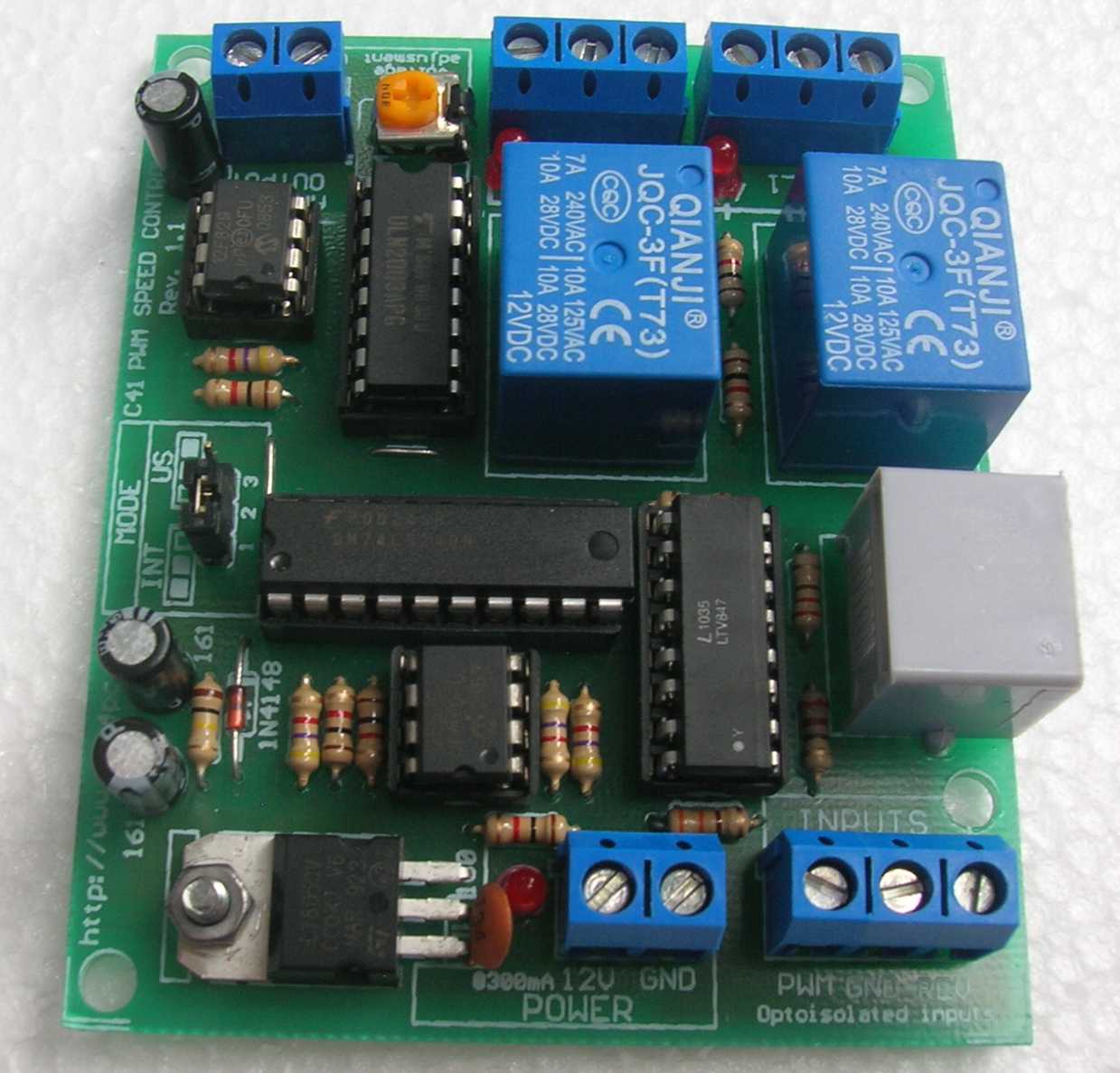
http://www.cnc4pc.com/Store/osc/product_info.php?cPath=25&products_id=303


  • Inputs a PWM and outputs an analog 0-10VDC.
  • Has two relays that can be used to control the direction and enable and disable the drive. 
  • Uses only two pins, one for PWM and one for direction. It is the presence of absence of the valid PWM signal what would start/stop the spindle. 
  • Jumper to select mode of operation, US or International mode. On US mode, one relay would be used to start CW and the second one to start CCW. On International mode Relay 1 will start/stop, and Relay 2 will determine the direction of rotation. 
  • Optoisolated output signals. The analog and CW/CWW signals are optically isolated, so this board can be used with drives that make grounds common with the mains that drive the VFD or motor. 
  • RJ45 Connector fast installation.
_________________________________

FTDI CABLE USB RS485 WIRE END 1.8M
RS485 USB to bare wire connector for controlling the ABB 9xxx series with RS485 adaptor
DigiKey part: 768-1041-ND
$36.14

Friday, 1 November 2013

Squaring the column

Before I embark on cutting any high tolerance parts with the mill I think it is worthwhile adjusting the column for perpendicularity. I don't have a cylindrical square which would be the reference of choice for this task. They are fairly cheap, but I can't see much use for one other than this job for moment. I do have a cnc 4.5" angle plate (cnc in this case being cheap n' cheerful) which I think will do. Given the quality, it is pretty unlikely to be terribly square, but it will at least be consistently not square. By measuring once, rotating the tool 180 degrees around the axis of measurement and then measuring a second time, the bias of the tool will be revealed. This is a similar technique to the calibration of water levels. Measure any nearly flat surface with the level, flip the tool around and measure again. The bubble should be in the same position no matter which way round the tool is.

So here is the setup on the table. I bolted the angle plate down and marked its position on the table and the section of the surface that was measured. Once the measurement is done, I flip the plate 180 degrees and realign it with the marks.


Same thing for the X axis direction


The results show that the angle plate is around 2 thou off square over 4.5" and that the column is off by about ten thousandths with respect to the X axis and two or three in Y. I really should do a series of measurements and take an average, but until I'm certain the column doesn't have to come apart again and I get myself a 10 thou test dial indicator I'm only interested in getting within a couple of thou.