Tuesday 17 December 2013

Power draw bar


PCNC 1100 Power Drawbar


Tormach's design uses a stack of three 100mm cylinders to compress another stack of 4 pairs of opposed belville washers.


Article about duplicating the Tormach Power drawbar:

http://danielbauen.com/make/index.php/tormach-milling-machine/tormach-power-draw-bar/


SMC cylinder CQ2B100x12-3 (Tormach uses a Chinese knock-off ):

http://www.smc.eu/portal/NEW_EBP/05)Standard_Air_Cylinder/5.2)Estandard_Air_Cylinder_/g)CQ2/CQ2_EU.pdf


Alternative cylinder from Fabco:


http://www.eartaker.net/machining/milling/zx45.php

The cylinder used for this machine is a Fabco Multi-Power MP3x1x3x1FF

Fabco catalog for stacked cylinders:

http://www.fabco-air.com/pdf/Sec_5.pdf


However, based on Daniel Bauen's experience:

"I don't believe that a Air Piston/Bellville washer power draw bar is a good design for the TTS style tool holders. The Bellville washers allow the tool holder to be pulled out, even when providing the theoretically necessary retention force. Tightening a rigid draw bar to the correct torque provides much better retention. This leads me to believe that a torque type power draw bar would be better. I may consider replacing this draw bar in the future with a impact style power draw bar. The downside is that the hex at the top end of the draw bar tends to wear out."

I think we are back to the impact design. Which has the merit of not requiring an expensive cylinder (the harbor freight wrench can be had for $15). Additionally, the Tormach design uses a flanged nut that for the cylinder to pull against which means that there is no load on the spindle bearings. The spindle on the RF45 is not threaded, which means spindle would likely have to be modified.


Controller box IO panels

Input output panels for the steppers and the proximity sensors. First, a quick drawing based on the Bulgin connectors and the DB25 for the parallel cable to the computer. The A axis is for future use, so I made a knock-out version on a separate panel. Thinned the 3/32`aluminum slightly for the DB connector with a 1/2" end mill. Finding a mono-line font for the engraving was more challenging than I thought it would be - there aren't many good ones out there and for some reason, the scaling would get screwed up during the import of the DWG into the CAM software... 


Connectors used for the steppers and proximity sensors:


http://www.bulgin.co.uk/PDFs/Cat83_sections/Buccaneer-2010_mini.pdf

Available from Mouser.

Three positions used for the prox sensors and four for the steppers.

Not the most robust things in the world. Step on them and they break!


Shell:

Digi-Key Part Number708-1238-ND
Price BreakUnit PriceExtended Price
17.530007.53
256.67840166.96
506.16460308.23
1005.13710513.71
5004.623402,311.70
Quantity AvailableDigi-Key Stock: 459
Can ship immediately
Manufacturer

Manufacturer Part Number

PX0800

DescriptionCONN HSNG INSERT SHELL CABLE


Male:

Digi-Key Part Number708-1248-ND
Price BreakUnit PriceExtended Price
18.390008.39
257.71920192.98
506.80760340.38
1005.71350571.35
5005.166482,583.24
Quantity AvailableDigi-Key Stock: 181
Can ship immediately
Manufacturer

Manufacturer Part Number

SA3230

DescriptionCONN TERM INSERT 3POS PIN SCREW
Lead Free Status / RoHS StatusLead free / RoHS Compliant


Monday 16 December 2013

Spindle control and additional IO research

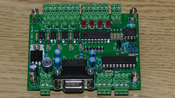
The CNC4PC board is near capacity in terms of IO. There is only one input and one output available. This makes it impossible for the moment to add the Variable Frequency Drive (VFD) for controlling a 3phase spindle motor and to add a front panel control interface for spindle, coolant pump etc.

A possible solution would be to add additional IO via ModBus over serial with or without an additional dedicated spindle control board. The ABB ACS 141 VFD requires a 0-10V control signal for speed and 12V logic for enable, direction and start/stop.

IO solutions:


  • 4 digital inputs, opto-isolated, with LED indicator. 
  • 4 digital outputs, open collector, 500mA, LED indicator, protection diode. 
  • 2 analog inputs, 0-5V, 10bit resolution. 
  • 1 analog output, 0-10V, 10mV resolution, 50mA drive capabillity. 
  • Wide operating voltage range, 15-30V 


http://www.homanndesigns.com/store/index.php?main_page=product_info&cPath=2&products_id=4


The I/O capability of the ModIO is;
Firmware upgradeable via Serial port.
  • 8 discrete inputs. Active low with internal pull-ups 
  • 8 discrete outputs capable of driving relay coils 
  • 2 MPG inputs that use discrete inputs 3&4 and 5&6 
  • 3 Analog inputs, 0 -5v dc, 10 bit resolution 
  • 1 Character LCD driver for 20x4 LCDs 
  • 1 Interface for DigiSpeed controller 
  • 1 Expansion bus interface for adding additional I/O modules. (to be added) 

Spindle control solutions:


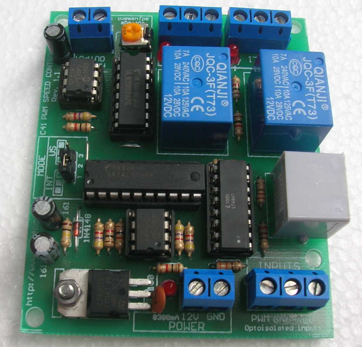
http://www.cnc4pc.com/Store/osc/product_info.php?cPath=25&products_id=303


  • Inputs a PWM and outputs an analog 0-10VDC.
  • Has two relays that can be used to control the direction and enable and disable the drive. 
  • Uses only two pins, one for PWM and one for direction. It is the presence of absence of the valid PWM signal what would start/stop the spindle. 
  • Jumper to select mode of operation, US or International mode. On US mode, one relay would be used to start CW and the second one to start CCW. On International mode Relay 1 will start/stop, and Relay 2 will determine the direction of rotation. 
  • Optoisolated output signals. The analog and CW/CWW signals are optically isolated, so this board can be used with drives that make grounds common with the mains that drive the VFD or motor. 
  • RJ45 Connector fast installation.
_________________________________

FTDI CABLE USB RS485 WIRE END 1.8M
RS485 USB to bare wire connector for controlling the ABB 9xxx series with RS485 adaptor
DigiKey part: 768-1041-ND
$36.14

Friday 1 November 2013

Squaring the column

Before I embark on cutting any high tolerance parts with the mill I think it is worthwhile adjusting the column for perpendicularity. I don't have a cylindrical square which would be the reference of choice for this task. They are fairly cheap, but I can't see much use for one other than this job for moment. I do have a cnc 4.5" angle plate (cnc in this case being cheap n' cheerful) which I think will do. Given the quality, it is pretty unlikely to be terribly square, but it will at least be consistently not square. By measuring once, rotating the tool 180 degrees around the axis of measurement and then measuring a second time, the bias of the tool will be revealed. This is a similar technique to the calibration of water levels. Measure any nearly flat surface with the level, flip the tool around and measure again. The bubble should be in the same position no matter which way round the tool is.

So here is the setup on the table. I bolted the angle plate down and marked its position on the table and the section of the surface that was measured. Once the measurement is done, I flip the plate 180 degrees and realign it with the marks.


Same thing for the X axis direction


The results show that the angle plate is around 2 thou off square over 4.5" and that the column is off by about ten thousandths with respect to the X axis and two or three in Y. I really should do a series of measurements and take an average, but until I'm certain the column doesn't have to come apart again and I get myself a 10 thou test dial indicator I'm only interested in getting within a couple of thou.


Wednesday 23 October 2013

Prox sensors

Research for proximity sensors

The Omron proximity switches that are going to be implemented are 12V/24V E2E-X5MF2 which are PNP-NC (normally closed). Data sheet here

They were bought to replace some surplus E2E-X2ME1-M1 which are NPN - NO (normally open). 


The normally closed configuration is far easier to implement with the cnc4pc breakout board.

Circuit diagram for hookup:


My pin assignments for future reference:

Sensor cable > Cable strand # > task (Control box wire colour)
blue               >      1                > 0V (blue)
brown           >      2                 > +24V (yellow)
black             >      3                > signal (green)


Connecting 3-wire PNP outputs in series:

Click to enlarge - SeriesConnPNPtransOutputs

Note from www.ab.com:
Series connection of 3-wire PNP output devices requires each device in the series to supply power to the next device with the last device in the chain supplying power to the load. Because each device supplies power to the next, response time is equal to the response time of the first sensor plus the sum of the turn on times of the others. The output of each sensor must be capable of supplying the peak load currents of subsequent sensors plus the current of the load. To overcome the internal supply capacitance of subsequent sensors, a low value (10 ohm) resistor is sometimes required in series with each.


A few brackets and new holes in the column later and here is one half of the Z axis. I can get away with using only a single sensor with two adjustable stops made from stainless rod. I milled a flat on the sections of rod so that the sensor "sees" more material as it crosses the threshold; perhaps this is not necessary (but it looks nice).


In the bottom if the frame below you can see piece of green masking tape. This is a little trick I learned from some conservation staff in a museum where, for obvious reasons, dust control is a big deal. Whenever they drilled into a wall they would tape a pouch made from scrap paper or newspaper right underneath the hole to catch the dust before it fell onto the floor. No cleanup afterwards [hand slap to the forehead]!!! 


The next question is how to splice the sensor cables to extensions. The location of the connections is going to be within the work area of the mill which means, if coolant is going to be used, that they have to be watertight. One possibility for this are TE MiniSeal Splices.

Available from Mouser at a mere $2 a pop!

http://ca.mouser.com/_/?Keyword=miniseal+wire+splice&FS=True
The D-436-36 model is for 20-26 AWG wire.

Tuesday 22 October 2013

Finished counter balance

Here is the finished system. The project was premised on the availability of close-assist springs - which turn out to be about five times the price of the 'regular' ones. So one redesign later...


The head weighs around 220lbs and the Z slide probably another 40 - 50lbs. The gas spring (from Mcmaster) has close to 10" of travel and a 225lb rating. However, the head travel is around 17", so I set the spring side up with an extra pulley to halve the travel, but at the expense of doubling the load; so the spring will actually see around 500lbs. In practice however, presumably because of the cumulative friction (the ways, chain and all the bearings) the system holds the head even when the stepper is not powered. I angled the chain away from the axis of the spring slightly with the intention of equalizing the radial loading. However, thinking about again, I'm not sure this was the best plan. The whole setup is adjustable so I may move the chain in further to reduce the angle or replace the single spring with a pair that are offset to generate stability in the weak axis. But if it ain't broke...


Sunday 20 October 2013

Other people's RF 45 projects

I set out this afternoon to research limit switches. I didn't find much, but I did come across some excellent projects that I hadn't seen before (but wish that I had looked at before starting this one!)


Rlberg (Bob Campbel?)'s conversion underway here: 

http://www.rlberg.com/RF45.html

Lots of good ideas and some very nice controller units.


And another here from JRouche on Home Shop Machinist (though this one has been running since 2006... so don't hold your breath :)

http://bbs.homeshopmachinist.net/threads/58904-Enco-square-column-(RF-45-clone)-CNC-build/page5


Nice article from Graetech on upgrading the bearings in the spindle and gear box. 

http://www.graetech.com/index_files/Page975.htm


Another excellent conversion, though the site is hugely annoying - you have to be a member to look at images - wtf?

Would you believe it? Machinetoolswarehouse has a 3ø replacement motor for the MD001 for $149.... Hmmmmmm. 

https://www.machinetoolswarehouse.com/xcart/catalog/Motor-3-phase-2-hp-p-16246.html?keep_https=yes


Clever Dutch guy with air tool power draw bar, spindle lock and drill stop.

http://m.youtube.com/watch?v=4oL-XcKPiKg&feature=related&desktop_uri=%2Fwatch%3Fv%3D4oL-XcKPiKg%26feature%3Drelated

Saturday 19 October 2013

Counter balance

As with quite a few of these mini-projects for the conversion, a big part of the challenge is figuring out a temporary solution for problems that require the machine itself to resolve permanently. The counterweight system is a case in point. I didn't have anything conveniently shaped and heavy enough to offset the mass of the head. So instead, I put together a Rube Goldbergesque arrangement of improvised pulleys (shackles with bits of tube for rollers) and some more plywood scraps to make a block and tackle. This part worked fine, generating more than enough resistance with a single piece of 1" steel plate.


The idler sprockets directly above the Z-slide proved more troublesome. There is no space to put an axle all the way through as the support posts for the stepper mount interfere. Consequently, the sprockets have to be bolted onto the mounting plates creating a cantilever condition which generates enough torque to significantly bend the 1/2" birch plywood. Even with an F-clamp installed, the bending was enough to make the chain start to misfeed occasionally!


Still, it works well enough to actually cut parts using all three axes for the first time. 


The first parts cut are of course the necessaries for the permanent version of the counter-balance system.


Friday 27 September 2013

Way covers

Notes and research on way covers


http://www.cnczone.com/forums/general-metalwork-discussion/58425-first-home-made-way-cover-bellows.html

___________________

http://www.franksworkshop.com.au/CNC/Bellows/Bellows.htm

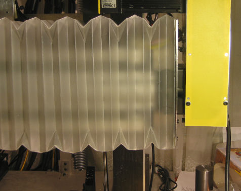
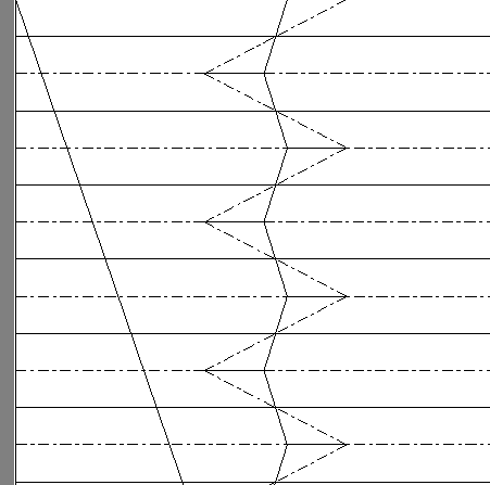
Folded polypropylene !


Optimized folding pattern holds its shape maximizes extension vs compression ratio


http://my.net-link.net/~jsmigiel/bellows.html


Update 2013 10 19

I needed a quick solution to get up and running, so I threw together a couple of large scraps of leather and aluminum. Works well enough for now! The only serious drawback is that they get sucked up into the shop vac when cleaning up. A couple of lateral stiffeners would resolve this. Perhaps they could also be U-shaped to force the leather down and around the ways...


Sunday 22 September 2013

Last Z parts

Fixed bearing mounting plate. I fortuitously found a new NSK bearing on eBay for which it would appear my surplus THK ball-screw journal was designed for. The label on the box for the Z ball screw is:

THK
Lm System
Model: BIF2504E-10RRG0+895LC2
Serial  KX07G01373

https://tech.thk.com/en/products/pdfs/en_a15_188.pdf

Although some of the info in that PDF is a little contradictory. The dimensions seem correct for the 2504-10 "semi standard" size, but the flange shape is different...


Motor mounting plate. Note that both have the CNC signature rounded corners that are essentially impossible (I.e. far too much trouble) to do on a manual mill.


A second mounting plate for the top of the column. This is sligtly redundant, but the bearing is thicker than the first plate and the mounting position (which I definitively established only after tearing down the column) would require cutting out an inch or so of the casting with hand tools. The second plate also allowed me to integrate a counter-balance design for the head, which I had neglected to think about when I cut the first plate.


Lastly, the ball-nut mount. The X axis screw came with a nut-mount which I just couldn't use in that tiny space inside the saddle. It is well made and seemed a shame to waste so I came up with a strategy to reuse it. I didn't have any 2" Mic 6 stock on hand, but making the extension for the mount out of two 1" pieces was pretty straight forward. The tube in the middle fits snugly into the hole in the Z slide that was a generous clearance fit for a 13mm bolt. I'm using a 1/2" bolt instead . The tube will do the job that the two taper-pins were doing in the initial design I.e. pin the nut-mount to the slide while the bolts hold it in the correct position. However, because there is now only one "pin", the nut is still free to rotate so it can be aligned perfectly along the axis of the screw. I just didn't see any way (or real need) to get the holes for two existing pins correctly positioned. Instead I'm replacing the pins with a couple of 1/4-20 bolts for extra (and likely superfluous) holding power.


Thursday 19 September 2013

Counterweight planning


Page to collect notes and references for the head counterweight system. The head weighs around 100Kg, which translates to a lot of permanent down-force that the Z axis will have to contend with. A bigger motor is the easy way around this, but there is also the issue of wear on the screw. I am looking at this now so that I can plan ahead while I make the last mounting plate for the top of the column.

Thomas Powell's solution using gas springs and garage door pulleys.

Print photo at home

Print photo at home

http://imageevent.com/tppjr/mill/rf45dovetailmill/zaxiscounterweight?p=0&w=1&z=2&c=4&m=-1&s=0&y=1&b=10&l=5

The machinetoolswarehouse cnc version of the RF45 which doubles as a training machine for body building ;-).   Its actually pretty serious: Hiwin linear slides, servos, better spindle bearings, VFD 3phase motor etc. All this can be yours for ~$12k... ...which is why I'm doing this the hard way!


I'm not completely convinced by the garage door pulleys, but the gas springs seem more elegant to me. So chain and sprockets plus gas springs it shall be.

Mcmaster idler sprocket:


353/8"200.640"2.59"0.72"__6663K2321.95


Above drawing doesn't show the Pitch Diameter. List of said measurements:

http://ablproducts.com/35-chain-sprocket.html


Update 2012 9 26

The counterweight project can no longer wait! I installed the Z axis with the column on the work bench to make things easier; way more pleasant than perching on top of a ladder. As soon as I was done I put the column back on the base and the head back on the column. As I was letting the tension off the chain block I discovered that the head will now turn the screw under its own weight - so without power the stepper the head will crash into the table!

Couple of 3/8" threaded stainless studs with flats and holes for #35 chain connectors.


As a temporary fix to get up and running I threw together a couple of pieces of plywood and some sprockets with 1/2" bolts and rod for axles.


The trouble is that I don't have anything heavy enough in a convenient form factor to act as a counterweight. The bucket-o-scraps just isn't going to cut it!


Tuesday 17 September 2013

Lapping done

Having finished all the parts I could for the Z without further measurements, I dismantled the entire machine again so I can finish lapping the ways and to figure out how to install the Z screw. Lapping is slow work. Its not so much the lapping bit as the cleaning between grits. It took two days, a small amount of diesel, three entire rolls of paper towel and copious beverages to lubricate the operator to get this done. 


The hole at the top end of the column needed to be enlarged a wee bit to get the flange of the ball-screw to fit. The tools of choice: a round file and an air grinder with an hss bur bit. I also took the time to clean up the inside of the column casting which had some pretty nasty, errr, crap for want of a better word, that could potentially interfere with the ball-nut.


Measuring up the Z slide to design the ball-nut mount. I'm using a dial indicator again to measure the layout of the taper pins and the central mounting hole so that I can match up the new ball-nut mount. Zero the dial against a reference, zero the height gauge, move the indicator down to what needs to be measured. Using the indicator makes it far easier to find the maximum or minimum of a circular part.


One shot oiler plumbing

I bought a Taiwanese one-shot pump on e-bay for $50 - it seems to be pretty good quality. The out port is BSPP 1/8" I believe.


Reference chart for BSPP aka G thread sizing:
http://www.marylandmetrics.com/tech/bsppthreadspecs.htm

From there I want to use 10mm pipe to run to the manifolds because I have plenty of leftover tube kicking around. However all the Parker flow control valves and the other fittings are 1/4 NPT, so this ends up being a bit of a mishmash of standards!

Parts list from MettleAir for what I don't have:

Version 1 - using Parker flow control valves (of which I'm missing one and two are not as advertised on ebay)

1   - MTC 10-G01              10mm x 1/8 BSPP
5   - MTC 10-N02              10mm x 1/4 NPT
10 - 122-B                       1/4 NPT hex nipple
10 - MTM 1/4                   1/4x1/4 push-fit bulkhead
2  - 121-B                        1/4 NPT plug

Version 2 - using pneumatic flow control + check valves instead (I don't have to make the manifolds this way and I don't have to source more Parker valves)

1   - MTC 10-G01              10mm x 1/8 BSPP
1   - MTC 10-N04              10mm x 1/2 NPT
2   - AM30-250-5               2 x 1/2 NPT in 5 x 1/4 NPT out
1   -  122-D                      1/2 NPT hex nipple
1   -  121-D                      1/2 NPT plug
9   -  MSC 1/4-N02            1/4 x 1/4 NPT meter out flow control valve
9   -  MCVU 1/4                1/4 check valve

In addition, I will plan ahead for the air requirements. These are:

Air jet for the spindle
Fog coolant, also for the spindle
Power draw-bar
Line for a blower to clean off the table etc
One spare

So a 2 in 5 out manifold would be a good place to start.

Parts list for the missing stuff for this:

1   -  122-D                     1/2 NPT hex nipple
1   -  AM30-250-5             2 x 1/2 NPT in 5 x 1/4 NPT out
1   -  121-D                     1/2 NPT plug
10 -  MTPP 1/4                1/4 plug (I need five but they are cheap...)
10 -  MTPP 10                  10mm plug (don't strictly need these but...)


Here is the assembled manifold. The check valve plus the meter-out flow control valve are equivalent to the Parker flow-control valve but are significantly cheaper and far more compact. I plumbed in the X axis ways and ball-screw. Everything seems perfectly satisfactory. Having done this with NPT, I will be using BSPP G thread standard fittings for all future pneumatics projects. I think is it far superior to NPT. Firstly, the thread is parallel and therefore requires far less cutting force than the tapered NPT. Secondly, the seal is established by an o-ring not Teflon tape and just works. I have two (small but annoying) leaks in two recent projects using NPT which I will have to take time to fix and which just wouldn't have been an issue had I used BSPP. Live and learn :)